AI Assistant
Notifications
Clear all

Hydrostatic vessel

2 Posts
2 Users
0 Reactions
2,617 Views
Posts: 1
Topic starter
Translate
English
Spanish
French
German
Italian
Portuguese
Russian
Chinese
Japanese
Korean
Arabic
Hindi
Dutch
Polish
Turkish
Vietnamese
Thai
Swedish
Danish
Finnish
Norwegian
Czech
Hungarian
Romanian
Greek
Hebrew
Indonesian
Malay
Ukrainian
Bulgarian
Croatian
Slovak
Slovenian
Serbian
Lithuanian
Latvian
Estonian
(@chengu)
Unpaid Intern
Joined: 3 years ago
[#1688]
image

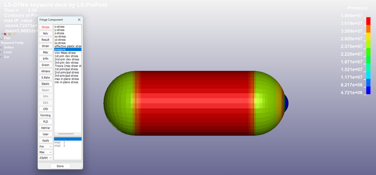
I made vessel model and put pressure by load-segment set.

The result of pressure is that picture. I wonder why I put constant pressure for each node but the pressure of each node is different.
Also, I wonder why the model moved to right.


1 Reply



Negative Volume
Posts: 681
Admin
Translate
English
Spanish
French
German
Italian
Portuguese
Russian
Chinese
Japanese
Korean
Arabic
Hindi
Dutch
Polish
Turkish
Vietnamese
Thai
Swedish
Danish
Finnish
Norwegian
Czech
Hungarian
Romanian
Greek
Hebrew
Indonesian
Malay
Ukrainian
Bulgarian
Croatian
Slovak
Slovenian
Serbian
Lithuanian
Latvian
Estonian
(@negativevolume)
CEO
Joined: 8 years ago

You are applying a pressure that doesn’t take into account material property or geometry of the part. Your resulting “pressure” from the fringe plot will be different.

https://ftp.lstc.com/anonymous/outgoing/support/FAQ/visualizing_applied_pressure


Reply


Share: